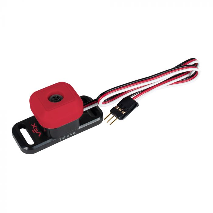
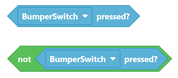
A bumper switch has a spring-loaded button which can recognize when it is pressed or released.
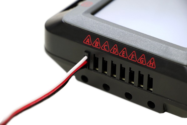
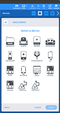
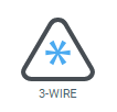
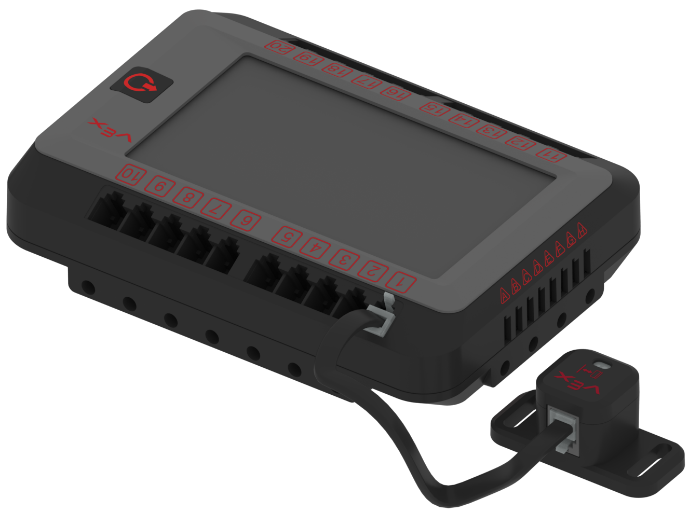
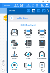
Add a bumper sensor to your robot and configure it in the devices window. It is a “3-WIRE” sensor and must be plugged into ports A-H.
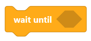
When you use sensors, it is best to put them in a WAIT UNTIL block rather than an IF-THEN-ELSE block. IF-THEN blocks only check the condition one time and then move on. To check the sensor more than once, you would have to put the blocks into a LOOP. By using a WAIT UNTIL block, the program will stop there and keep checking the sensor until the condition becomes TRUE. Then it moves on to whatever comes next in the program.
Task 1:
Wait for the bumper switch to be pressed (and released) then start driving slowly forward. Wait for the bumper switch to be pressed (and released) again and stop driving.
(Why is it important to always wait for the bumper to be released?)
Task 2:
Have robot switch between turning right and left whenever the bumper switch is pressed (and released).
Task 3:
Have the robot change speed whenever the bumper switch is pressed.
Optical Sensor (light)
An optical sensor can be used to determine the color of an object, the amount of ambient or reflected light, proximity, and gestures.
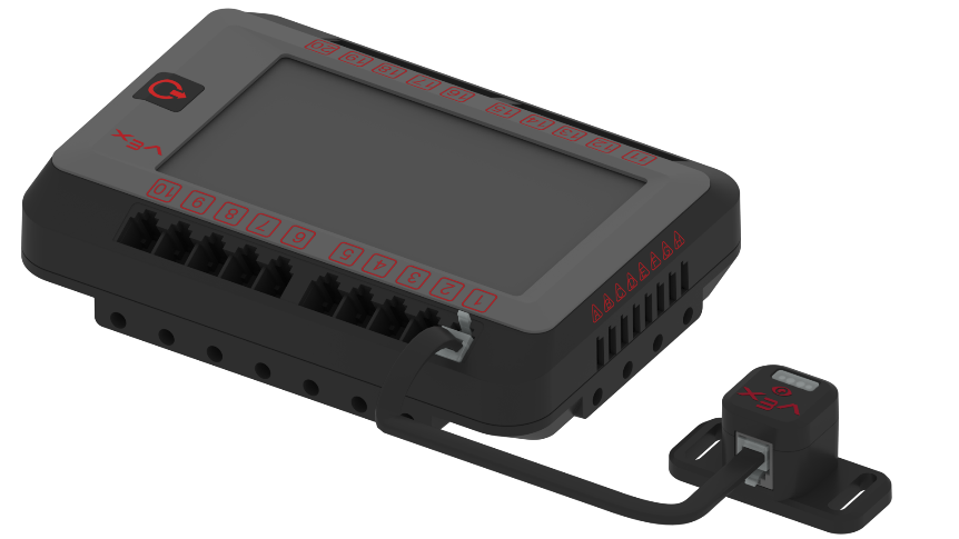
Add an optical sensor to your robot and configure it in the devices window. It is a V5 smart sensor and must be plugged in to ports 1-21 using a smart cable. If you want the sensor to see things on the ground, point the sensor down. If you want to see things in front of or above the robot, place it accordingly.
Task 1:
Using the optical sensor, drive to a white line and stop.
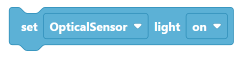
When using the optical sensor to see reflected light (colors), turn on the LED light built in to the sensor:
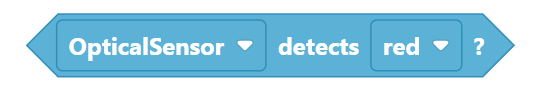
When looking for colors, sometimes the built in “color values” will work for you:
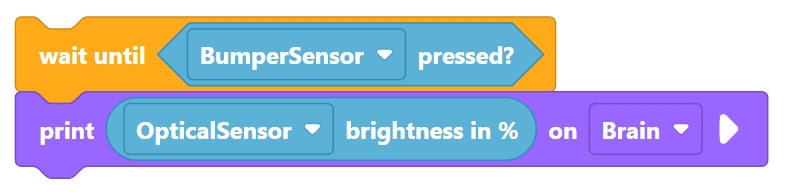
If they do not work, you will need to find out just how “bright” the color looks to the robot. The best way to do this is to write a simple code to show the brightness value on the robot screen:
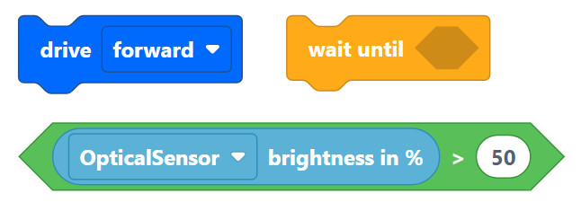
Then you can use the brightness value you saw in your program like this:
Task 2:
Use the optical sensor to drive to black line, turn around, drive to white line and stop.
Task 3:
Point the optical sensor to the ceiling and turn in circle when overhead lights are on, stop when lights are off. (Or you can use a flashlight.)
Task 4:
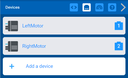
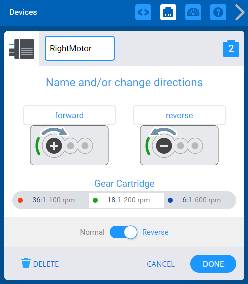
Use the optical sensor to follow the line. To do this, you will need to change from using a DRIVE TRAIN to controlling your LEFT MOTOR and RIGHT MOTOR separately.
You will also need to “REVERSE” the right motor (since the left and right motors are facing opposite directions on your robot).
Distance Sensor (laser)
A distance sensor uses a pulse of safe laser light to measure the distance from the front of the sensor to an object. It can also determine the relative size of an object (small, medium, or large) and calculate the approach speed of the robot toward an object.
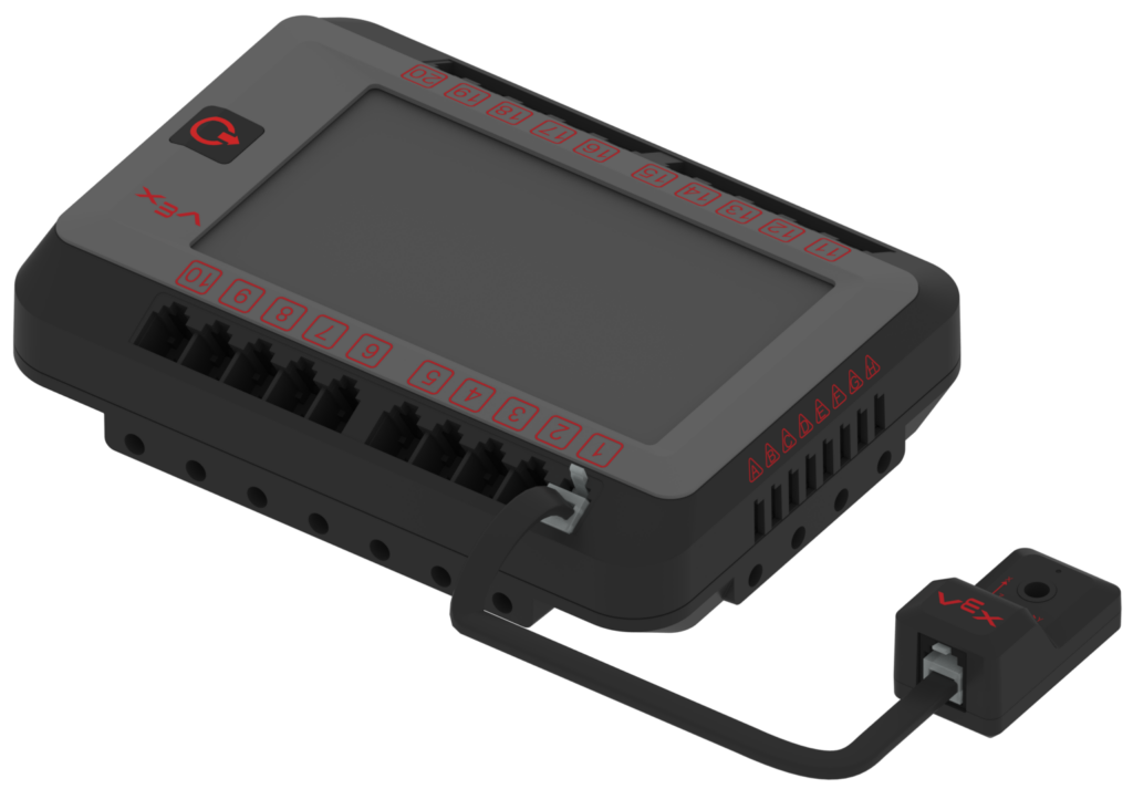
Add a distance sensor to your robot and configure it in the devices window. It is a V5 smart sensor and must be plugged in to ports 1-21 using a smart cable. Make sure you change back to using a DRIVE TRAIN like you did for the previous tasks:
Task 1:
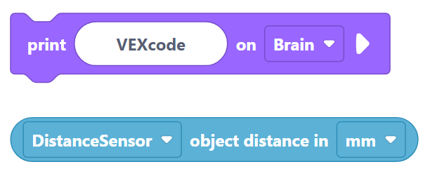
Using a bumper sensor and a distance sensor, print the distance to the floor on the screen in inches when the bumper switch is pressed.
Task 2:
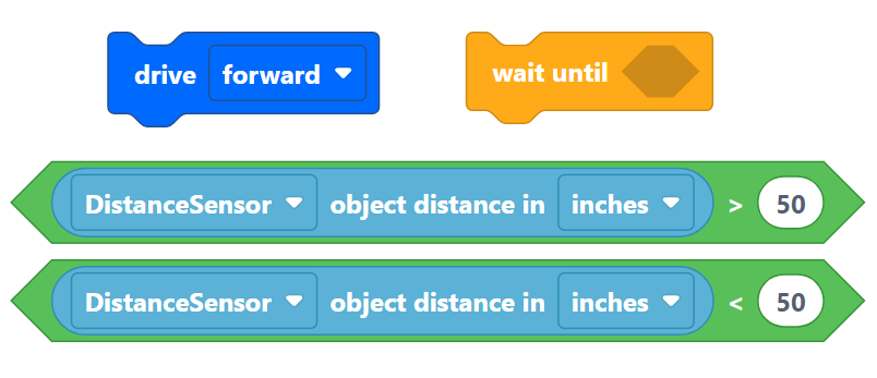
Drive forward until 1 ft from wall then back up until 5 ft from wall. (Sensor needs to be 4+ inches above the floor and facing FORWARD, not DOWN.)
How many inches would be in 1 foot? How many inches would be in 5 feet?
Task 3:
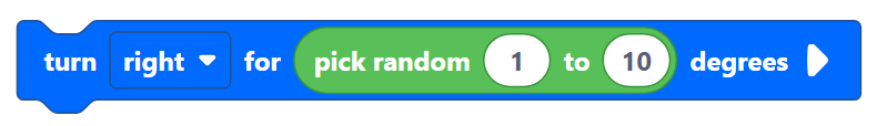
Drive until 8 inches from an object, back up, turn a random amount, and repeat.
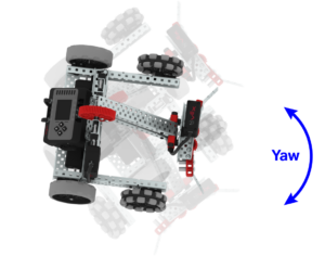
Inertial Sensor (gyro)
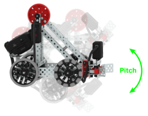
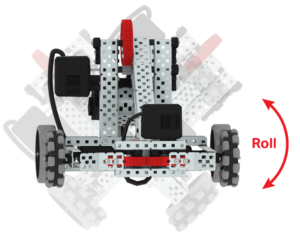
An inertial sensor is a combination accelerometer (how fast you are turning) and gyroscope (what direction you are facing). It works on three axes: X (pitch), Y (roll), and Z (yaw).
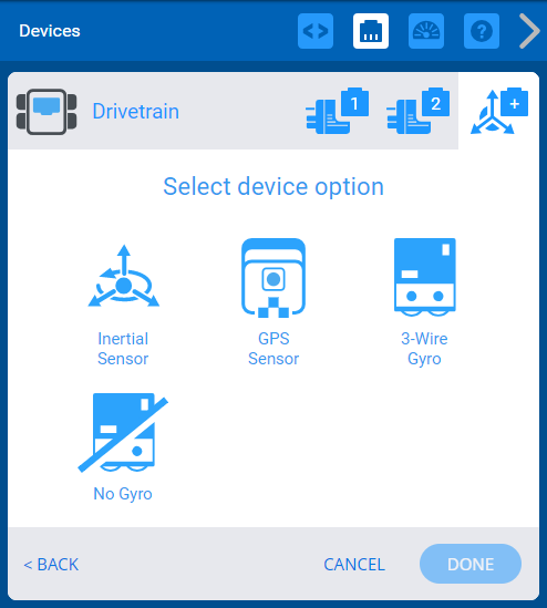
Add an inertial sensor to your robot and configure it in the DEVICES window. It should be attached flat onto the robot chassis and as close as possible to the center of the robot.
Task 1:
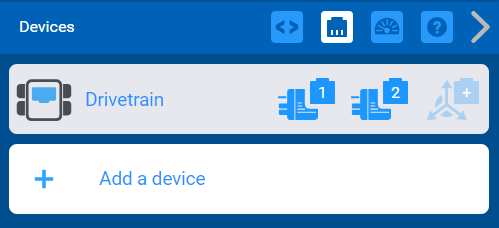
Set up your DRIVETRAIN to use the INERTIAL SENSOR. Try turning 90 degrees left, 180 degrees right, and 90 degrees left again. Did the robot move more accurately with the inertial sensor than with “no gyro” in the drivetrain?
Task 2:
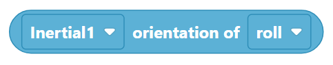
Disconnect your inertial sensor from your DRIVE TRAIN and add it as a separate device in the DEVICES window. Use the INERTIAL SENSING block to read your robot’s pitch, roll, and yaw.
Make the following text show up on your screen (or you could use colored squares in different positions on your robot screen):
When the robot is tilted forward, write “downhill”.
When the robot is tilted backward, write “uphill”.
When the robot is tilted to the left, write “left”.
When the robot is tilted to the right, write “right”.
Vision Sensor (camera)
If you have more time, you can explore the vision sensor. It is capable of detecting up to 7 colors at once (including multi-colored objects). The sensor can recognize colors and color patterns, follow a moving object, and collect information about the environment. You can even connect a phone or tablet through built-in WiFi to stream a live feed of what your robot is seeing.
Task 1:
Connect your Vision Sensor to a mobile device. Add it to the DEVICES WINDOW in your program. The following video will explain how to configure your sensor to detect colors. If you need more help, read through the resources from VEX for Using the Vision Utility with the Vision Sensor.
Task 2:
Colored cubes will be placed randomly around the robot. Make your robot scan for one of the colors, turn, and drive to that cube and stop.
You should have already configured your Vision Sensor to recognize the three different color cubes. Now use that information to help your robot find the block you want.
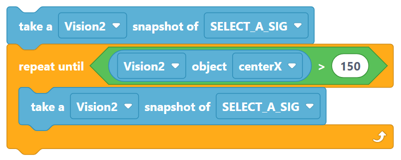
In your program, you will use the “TAKE A SNAPSHOT OF” block each time you look for your configured object. Start your robot turning (slowly) and keep taking snapshots until the object exists or until the object’s CENTER-X value is right in the middle of your VISION SENSOR. A REPEAT UNTIL block might be good to use in this situation. Also, note that the VISION SENSOR’s screen goes from 0 to 315. The “middle” of the screen would be around 157. Once your robot is lined up with the block, stop turning and drive forward to the block.
Task 3:
You can connect your Vision Sensor to a mobile device. (This is like having a “GoPro Camera” attached to your robot. You will see what it sees.)
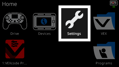
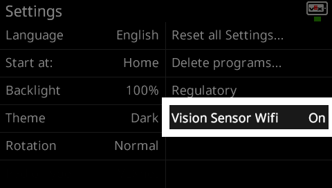
Verify the WiFi on the V5 Brain is turned on. Select the SETTINGS icon on the brain’s screen.
Go to the VISION SENSOR WIFI setting. If it is OFF, press it to turn it ON.
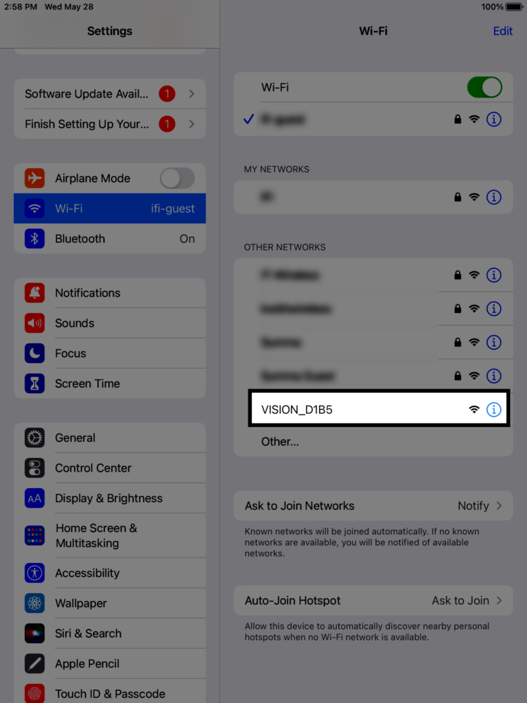
On your mobile device, go to your WiFi settings and look for a VISION SENSOR option. The sensor name will vary, but should always begin with VISION_…
Select the VISION SENSOR name and wait for it to connect.
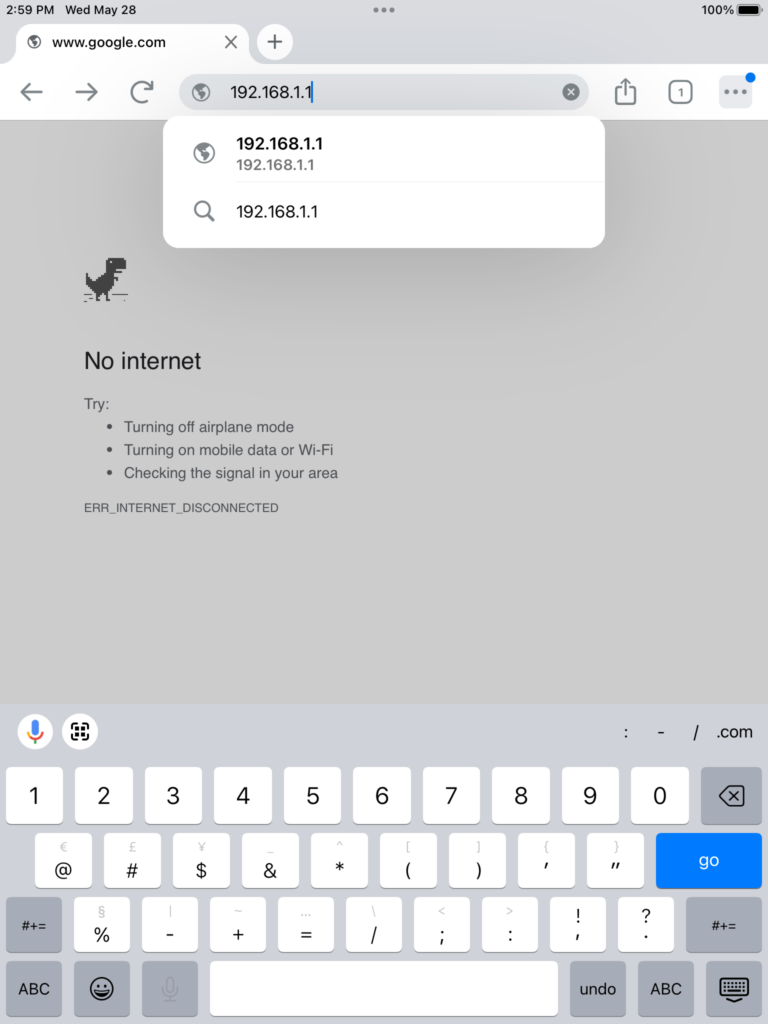
On your mobile device, open a browser window and enter 192.168.1.1 in the address bar.
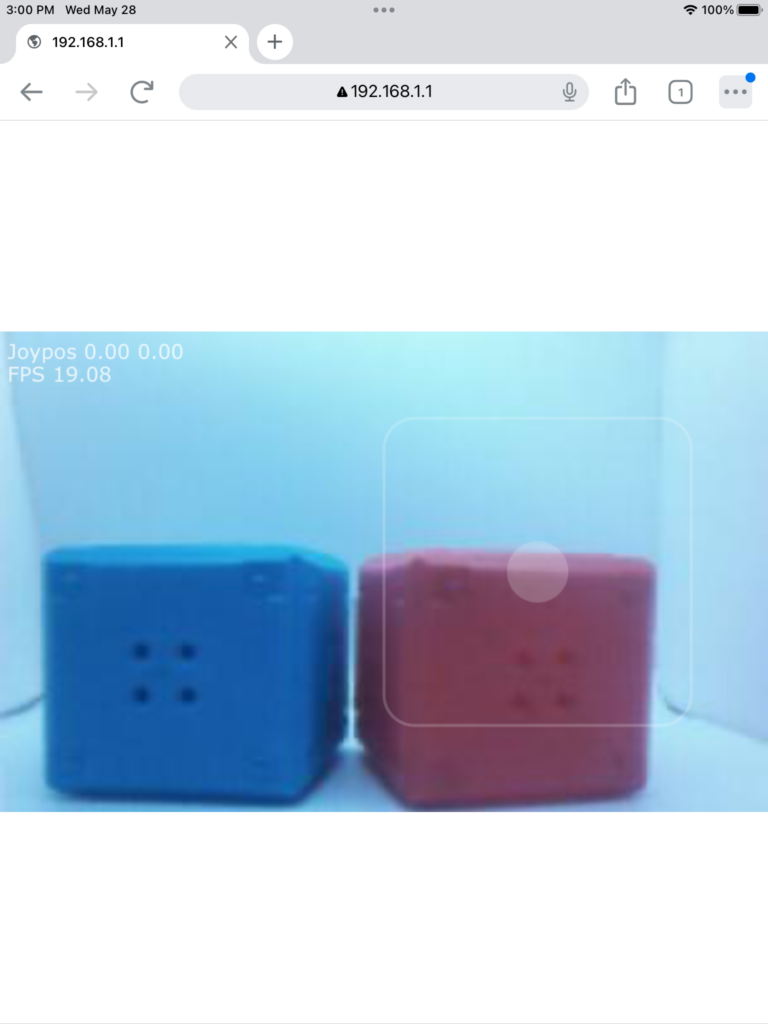
Camera data from the VISION SENSOR will now be shown in the browser window.
Once your mobile device is connected, can you “remotely” drive your robot around the field without standing next to the field?